
Common Peak Shape Distortions in HPLC and their Prevention
A chromatographer always looks forward to getting perfect shaped peaks for each and every analysis but in reality peaks get distorted due to numerous reasons. Distortions are frustrating but if proper corrective steps are taken peak shape distortions can be avoided.
Ideal Peak
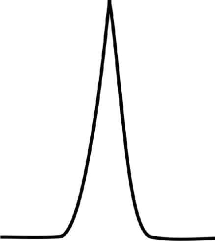
Ideal Peak
Flat Top Peak
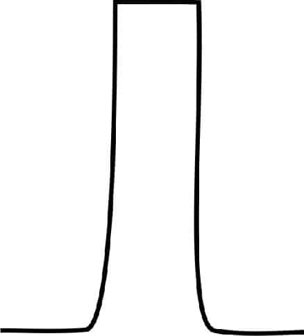
Broad Peak
A flat top peak response arises when the detector gets overloaded with the sample. In such case detector sensitivity is much higher and it gets saturated to give a broad flat top peak. One option is to attenuate the signal response (not a practical solution) as detection of other peaks will also get affected. A more viable option is to reduce the concentration of sample or volume of injection.
Peak Tailing
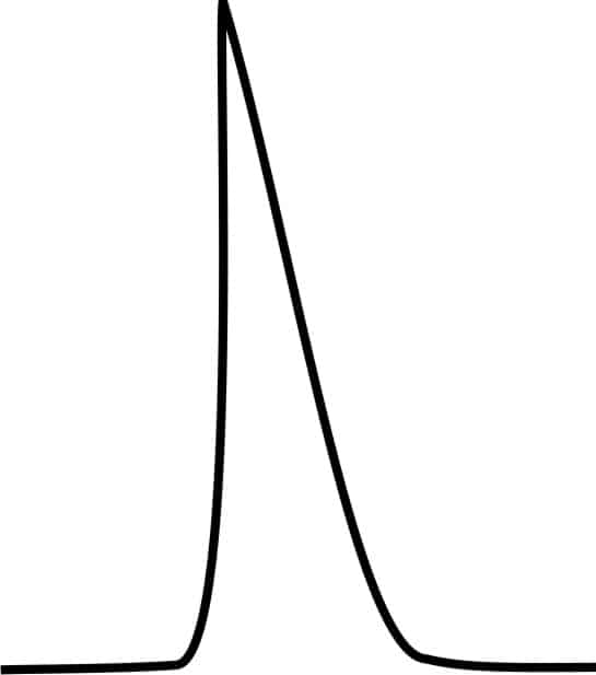
Tailing Peak
Peak tailing is a common distortion arising due to ionization of surface silanol groups to – Si-O - which provide cationic exchange sites. The solution lies in use of high purity grade silica support along with a selection of the recommended pH range 2-8.
Use of buffer control additives also limits ionization of silanol groups on the silica surface. Additives such as Trifluoroacetic acid (TFA ) an ion pairing agent helps suppress ionization. Buffer additives in the concentration range 10– 25 mM are sufficient for most applications.
Frit blockage or void formation can be prevented by filtering mobile phase solvents, use of inlet filters and replacement of pump seals before they begin to wear and release garbage particles.
Low purity silica often contains metal impurities which promote ionization of silanol groups. Use of high purity silica stationary phase helps in tailing due to chelation with metal ion in stationary phase.
Peak Fronting
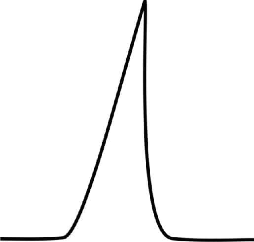
Fronting Peak
Peak fronting is less common in comparison to Peak tailing
Generally peak fronting as a result of channeling inside the column. It is best to replace the column or otherwise operate within the recommended pH limits.
Column overload can also result in peak fronting. Use dilute sample or reduce the sample injection volume.
Incompatibility of mobile phase with sample often results in peak fronting. Dissolve sample in mobile phase or another compatible solvent
Peak Shoulders and Split Peaks
| 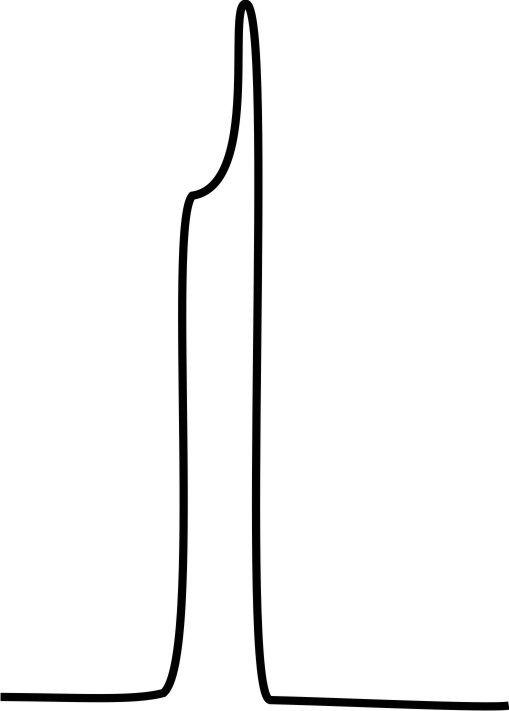
Shoulder Peak | 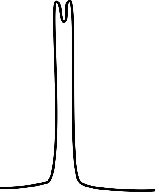
Split peak | | --- | --- |
Shoulder peaks and split peaks often result due to presence of two closely unresolved compounds.
Reduce sample size or use a diluted solution often resolves the split
Splitting off peaks is also caused by frit blockage. Reverse flow with 20 – 30 ml of mobile phase often resolves the peak splits.
Replace the blocked frit or the guard column
When split is caused due to presence of two closely eluting compounds use sample cleanup prior to injection
As you have seen above a number of causes of peak shape distortions are common such as pH control of mobile phase, blockage due to particulate contamination, blocked frits and column overload. The shape of the distortions can be improved by taking corrective steps and other recommended steps whenever necessary.
Please share your experience and leave your comments.